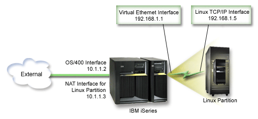
NAT can route traffic between your logical partition and the external
network using virtual Ethernet.
This particular form of NAT is called static NAT, and it will allow
both inbound and outbound IP traffic to and from the logical partition. Other
forms of NAT like masquerade NAT would also work if your logical partitions
do not need to receive traffic initiated by external clients. Like the TCP/IP
Routing and Proxy ARP methods, you can take advantage of your existing i5/OS® network
connection. Since you will be using IP Packet rules, you must use iSeries™ Navigator
to create and apply your rules.
The following illustration is an example
of using NAT to connect your logical partition to an external network. The
10.1.1.x network represents an external network while the 192.168.1.x network
represents the virtual Ethernet LAN.

In this pre-V5R3 example,
any existing TCP/IP traffic for the iSeries hosting partition runs over the
10.1.1.2 interface. Since this is a static map scenario, the inbound traffic
gets translated from the 10.1.1.3 interface to 192.168.1.1 interface. The
outbound traffic gets translated from the 192.168.1.1 interface to the external
10.1.1.3 interface. The logical partition uses the virtual interface (192.168.1.1)
and its own 192.168.1.5 interface to communicate with the server.
To make static NAT work, you need to first set up your i5/OS and Linux
TCP/IP communications. Then you will create and apply some IP Packet rules.
Use the following procedure:
- During the configuration of your logical partition, make sure you
selected to create virtual Ethernet. This is described in Configure
a logical partition.
- Create an Ethernet line description for virtual Ethernet. Note
the port of the hardware resource, because you will need it when you set up
TCP/IP in your logical partition. In the case of the above example,
assume the hardware resource is CMN05 with a port of 0 and although arbitrary,
the line description name is VETH0. CRTLINETH LIND(VETH0) RSRCNAME(CMN05)
LINESPEED(1G) DUPLEX(*FULL)
- Add a TCP/IP Interface for your virtual line description. Following the example, you could use: ADDTCPIFC INTNETADR('192.168.1.1')
LIND('VETH0') SUBNETMASK ('255.255.255.0')
Start your new TCP/IP
interface using the command STRTCPIFC INTNETADR(yourIPaddress) or STRTCPIFC
INTNETADR('192.168.1.1'), for the example.
- On your logical partition, set up networking using the instructions
or tools provided by your Linux distribution. Be sure to use the
correct IP address, subnet mask, port from step 2, and gateway IP address.
During
the TCP/IP setup in Linux, you will need to know your net or network device.
If you are running a 32-bit kernel version of 2.4.9 or less, the network device
is VETH plus the port number from when you configured an Ethernet line description.
If you are running a 64-bit kernel or a 32-bit kernel greater than or equal
to 2.4.10, the network device is ETH plus the port number. See Create an Ethernet line description for virtual Ethernet for more information. In the example:
- the interface IP address is 192.168.1.5
- the subnet mask is 255.255.255.0
- the gateway IP address is 10.1.1.3
- the network device is VETH0 or ETH0 depending on the kernel version
- Create another TCP/IP interface that connects to the external network. It should use the same line description as your existing external TCP/IP
interface. This interface will eventually perform the address translation
for your partition. Check to make sure your new interface communicates with
the external LAN properly. In the case of the example, this interface has
an IP address of 10.1.1.3 on a line description called ETHLINE.
- Start the external TCP/IP interface. STRTCPIFC
INTNETADR('10.1.1.3')
- You should now verify that your virtual Ethernet connection works.
From the logical partition, ping the Linux gateway and from i5/OS, ping
the logical partition. If the ping is successful, continue.
- Turn on IP datagram forwarding. This allows the i5/OS TCP/IP
interfaces to pass IP packets between each other. CHGTCPA IPDTGFWD(*YES)
- Connect to the server with iSeries Navigator. You must not connect
to the server with the NAT interface that you just created.
- Navigate your way to Packet Rules. Use the Packet Rules
interface to write at least three rules to enable static NAT. You need to
create two New Defined Address rules and a New Mapped Address rule.
- In the Packet Rules window, create a new rules file by selecting
New File from the File menu.
- In the New Rules file menu, right-click
on Defined Addresses and select New Defined
Address.
- Enter an Address name, the IP address of the logical partition,
and a type of Trusted. For the example, you would enter:
- Address Name = LINUXPART
- Defined Address = IP Address where your IP address equals 192.168.1.5
- Type = Trusted
- In the New Rules file menu, right-click
on Defined Addresses and select New Defined
Address.
- Enter an Address name, the IP address of the logical partition,
and a type of Border. For the example, you would enter:
- Address Name = SHELL
- Defined Address = IP Address where your IP address equals 10.1.1.3
- Type = Border
- Expand the Address Translation menu item
from the New Rules file menu window.
- Right-click on Mapped Addresses and select New
Mapped Address.
- Enter the Mapped address name, the To address name, and the
line name. You can leave the Journaling set to off. For the example,
you would enter:
- Mapped address name = LINUXPART
- To Address name= SHELL
- Line = ETHLINE
- Journaling = OFF
- Verify your rules by selecting Verify under
the File menu.
- Save your rules file.
- Upon successful verification, select Activate from
the file menu. Your static NAT rules are now active.
To test outbound communications, ping an external host from your logical
partition. Then from that external host, ping your logical partition to test
inbound communications.
