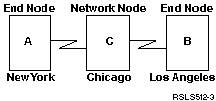
Example: Three iSeries systems using APPN
 In Figure 6, A and B are end nodes. The network node must configure
its network attributes to reflect that it is a network node. Each system must
configure the remote control-point name in the controller description that
represents the adjacent system. Also, A and B must indicate in the controller
description for the network node that it can be a network node. A and B must
add the network node to the server list in network attributes so that the
network node might act as a network server for both end nodes.
Note:
Neither end node needs to configure any information about
the other end node.
Figure 6. Three-system APPN network
Each list below represents a city within the network in Figure 6 above.
See the links in each list to determine the configuration requirements for
each system.
New York
Los Angeles
Chicago
 In Figure 6, A and B are end nodes. The network node must configure
its network attributes to reflect that it is a network node. Each system must
configure the remote control-point name in the controller description that
represents the adjacent system. Also, A and B must indicate in the controller
description for the network node that it can be a network node. A and B must
add the network node to the server list in network attributes so that the
network node might act as a network server for both end nodes.
