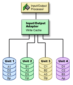
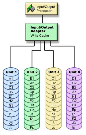
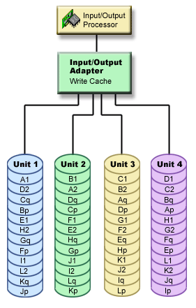
The following diagrams illustrate the elements of a parity set that contains four disk units. Each parity set begins with an input/output processor (IOP) that is attached to an input/output adapter (IOA), which contains the write cache. The IOA transmits read and write signals to the attached disk units.
P indicates the sections of the disk that contain parity data.
Q indicates the second stripe of parity data.
Note: The
second stripe of parity data is only associated with RAID 6 protection.
Figure 1. Example of how parity data is distributed with RAID
5 pre-V5R2 IOAs


Figure 2. Example of how parity data is distributed with RAID
5 post-V5R2 IOAs


Performance is improved by spreading the parity data throughout each of the disk units. The device parity protection that is spread throughout the disk units equals one disk unit of memory.
Figure 3. Example of how parity data is distributed with RAID
6


Performance is improved by spreading the parity throughout each of the disk units. The total amount of protection that is spread throughout the disk units equals two disk units of memory.