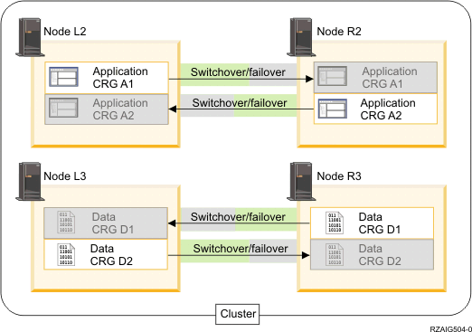
Use this example to create a more complex cluster that contains four nodes.
This example configuration provides the following:
- Two-way replication and failover
- Three-tier environment
- Applications and data move independently
- Backup is used for normal production of different workload

The four-node example shows the additional flexibility that is possible with an iSeries™ cluster. There are two application cluster resource groups (A1 and A2) and two data cluster resource groups (D1 and D2). The data associated with D1 is the critical data for the application associated with A1. The data associated with D2 is the critical data for the application associated with A2. Because this is a three-tier environment, the applications exist on the second tier (Node L2 and Node R2) and the data is separated into the third tier (Node L3 and Node R3).
| Cluster resource group (CRG) | Primary | Backup |
|---|---|---|
| Application CRG A1 | L2 | R2 |
| Application CRG A2 | R2 | L2 |
| Data CRG D1 | R3 | L3 |
| Data CRG D2 | L3 | R3 |
This enables mutual take-over capability at both the application and data levels. All four nodes are being used for normal production. They are also being used to back up other systems in the cluster. The two applications and their associated data should always be available in this cluster. The outage of any single node will not disrupt availability. In addition, the simultaneous outage of a node at the application level with a node at the data level will not disrupt availability.